

Low Voltage Switchgear Factory: Key Factors for Reliable Power Distribution
2026-11-02
When power fails, the weakest link is often the switchgear—and that's where factory precision matters more than most people realize. A low voltage switchgear factory isn't just assembling metal boxes; it's engineering the backbone of reliable power distribution. From busbar alignment to thermal management, every detail shapes how safely and consistently electricity reaches your equipment. At MOLDVOLT, we've seen firsthand how small manufacturing choices separate systems that endure from those that fail under load. This article unpacks the key factors that actually drive long-term reliability—so you can spot the difference before a costly outage does.
Engineering That Adapts to Real-World Load Profiles
Real load profiles rarely look like the tidy curves in a textbook. Motors stall, compressors cycle on and off, and entire sections of a facility switch from idle to full draw within seconds. Designing for those shapes means collecting field data early and letting actual demand patterns drive topology choices, not the other way around.
One practical approach is to treat the load as a time-varying envelope rather than a single worst-case number. That shift changes how you size thermal pathways, specify energy storage, and set control loop bandwidths. A converter that only hits its efficiency sweet spot at 80% load will waste energy and generate extra heat when the real duty cycle hovers around 20% for most of the day.
The payoff shows up in longer service intervals and fewer nuisance trips. When protection thresholds and response times follow the measured profile, systems ride through transients that would otherwise trigger false alarms. Engineering that adapts here is less about adding margin everywhere and more about placing margin where the load actually lives.
Busbar Design Where Temperature Rise Meets Its Match
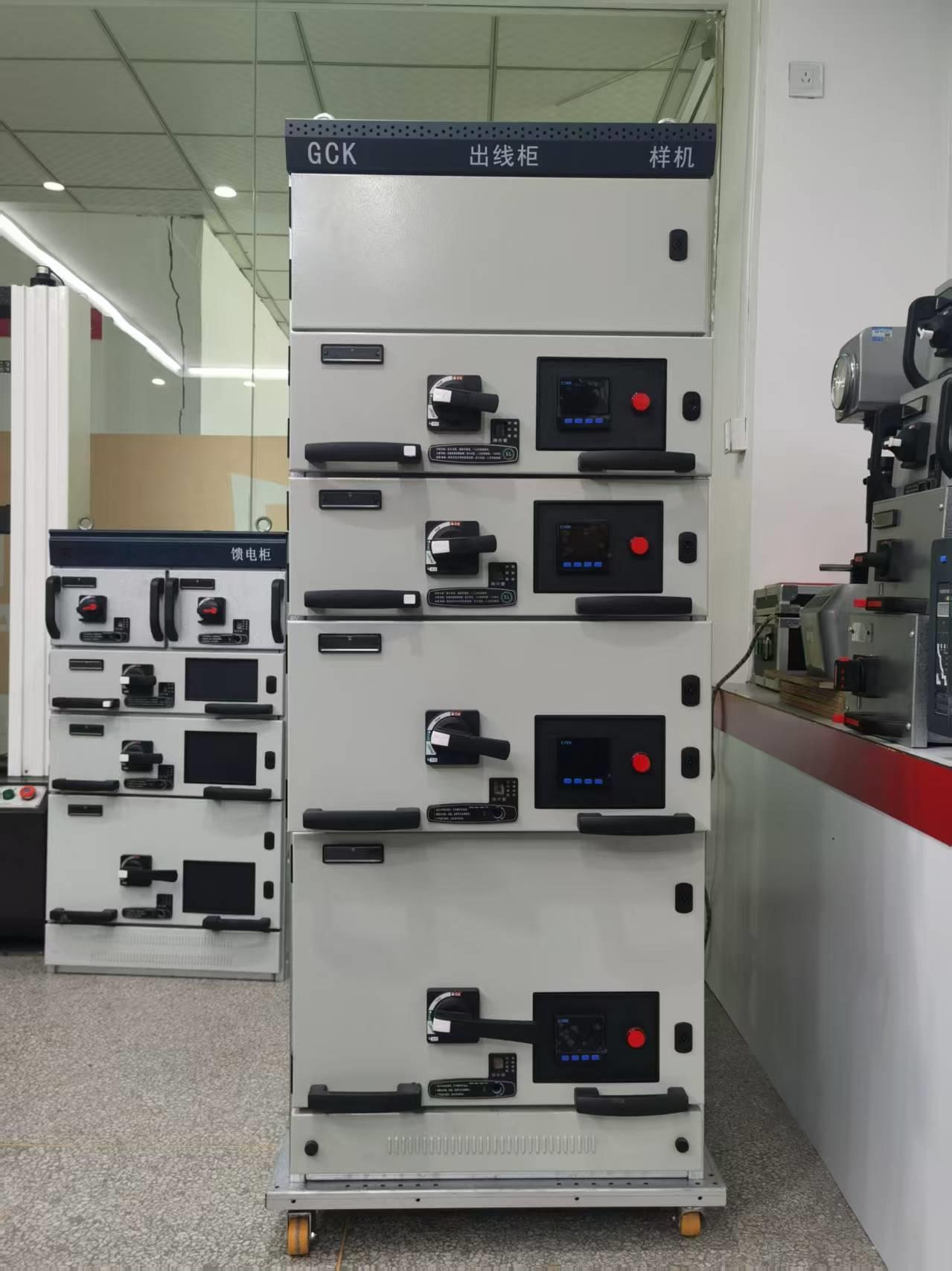
Copper remains the default choice for busbars, but the real gains in thermal performance come from questioning every assumption about its shape and surface. A flat bar with rectangular cross-section wastes material at the center, where current density drops and heat has nowhere to go but through the insulation. Shifting to a hollow or laminated profile changes the skin-effect penalty and gives cooling air a direct path across the conductor, which makes a measurable difference under continuous load.
Surface finish is often treated as a cosmetic detail, yet it determines how efficiently a busbar sheds heat into its surroundings. A rough, oxidized surface traps a thin layer of still air, raising the thermal resistance precisely where it hurts most. By contrast, a controlled matte finish or a thin ceramic coating improves emissivity without relying on bulky heat sinks. Even a modest rise in emissivity can lower the steady-state temperature by several degrees, which translates directly into longer insulation life and fewer hot spots at bolted joints.
The joint itself deserves more attention than it usually gets. Contact resistance creeps upward as surfaces expand and contract, and a poorly designed joint can become the hottest point in the entire assembly. Using conical spring washers, silver-plated contact pads, and a specified torque sequence keeps the interface pressure consistent, preventing the slow thermal runaway that shortens busbar service life. When these details line up, the temperature rise stops being an accepted penalty and starts behaving like a designed parameter.
Breaker Coordination Without the Guesswork
Breaker coordination has long been treated as a dark art—one that involves flipping through time-current curves and hoping the overlap doesn't bite you later. That approach works until a minor fault takes down an entire facility. A better starting point is to map the actual impedance path from the service entrance to the final branch circuit, then assign realistic fault values at each bus. When you know the available fault current at every level, you can stop guessing and start comparing breaker responses with purpose.
The real coordination happens on the curve sheet, but not as an exercise in matching shapes. Pick the downstream breaker first and anchor its trip characteristics to the load it protects—motor inrush, transformer inrush, or cable thermal limits. Then move upstream and select a breaker whose no-trip threshold clears the downstream device's total clearing time by a comfortable margin, usually 0.1 seconds or more for electronic trip units. This "top-down from the bottom" method avoids the common mistake of oversizing the main simply because it looks safer on paper.
Verification is where the guesswork usually returns. Instead of trusting nameplate settings, stage a primary injection test or use manufacturer software to model worst-case bolted faults and arcing faults. Record the sequence of operation for each fault location and adjust pickup, delay, or instantaneous override until the isolation target is met. When the test report matches the coordination study, you've replaced hope with a repeatable process.
Arc Containment Built Into Every Enclosure
The enclosure itself is not just a metal box—it's engineered as the first line of defense against arc flash events. Internal walls, reinforced seams, and pressure-relief vents are laid out to channel superheated gases away from the operator's normal working zone. Instead of relying on add-on barriers, the arc containment is baked into the structural geometry, which means every unit leaves the factory with the same level of fault protection, regardless of how it's configured on site.
During an internal arcing fault, temperatures can spike past 19,000°C in milliseconds. The enclosure's containment strategy focuses on two things: holding the pressure long enough to prevent door blow-off, and directing the remaining blast through designated exhaust paths. This isn't achieved with thicker steel alone—the hinge and latch systems are matched to the pressure curve, while internal partitions break up the plasma jet before it can reach cable compartments or adjacent cabinets.
Field reports repeatedly show that the difference between a contained arc and a catastrophic failure often comes down to how the enclosure handles the first few cycles. With built-in arc containment, there's no need to specify a separate arc-resistant kit or retrofit after commissioning. The safety margin is already part of the base design, so maintenance crews can work with confidence knowing the fault path has been thought through from the ground up.
From Factory Tests to Field Confidence
Factory tests often end at the loading dock. A device can pass every in-line check and still stumble once it faces uneven terrain, shifting temperatures, or operators with different habits. The gap between a clean pass on the bench and dependable performance in the field is where real confidence is built.
Closing that gap means looking beyond pass/fail reports. Teams that treat field returns, maintenance logs, and operator feedback as test data start to see patterns that no lab simulation would reveal. A connector that survives vibration rigs may still corrode faster near coastal salt air; a pump calibrated at constant pressure may behave differently under throttled valves. These are not failures of the original test, but signals that the test itself needs to evolve.
The strongest programs feed those field signals back into the factory floor. If a certain lot shows early wear in one region, the next production batch gets a targeted screening step. Over time, the line between factory test and field confidence blurs: the test stops being a final hurdle and becomes an early warning system. That shift is what turns a specification into a reputation.
Lifecycle Support That Outlasts the Warranty
Most manufacturers treat the warranty expiration date as the finish line. We see it as the starting point of a longer conversation. After the standard coverage period ends, our team continues to monitor device health, push over-the-air firmware improvements, and flag potential issues before they become failures. That means a unit purchased five years ago still receives the same attention to compatibility and security as one shipped last week.
Beyond software updates, physical parts remain available for years after a model is discontinued. Our spare-component inventory is planned around real-world usage data, not just projected sales curves. When a component does wear out, replacement instructions and direct engineering support are provided without requiring a new service contract. This keeps aging hardware productive, reduces unplanned downtime, and saves operators from the costly cycle of premature replacement.
FAQ
Look beyond basic certifications. A dependable factory backs its panels with rigorous type-testing, traceable component sourcing, and a willingness to share test reports. The assembly team should follow a documented quality plan, not just a final inspection checklist.
Busbars are the backbone. Using high-conductivity copper with proper cross-sectional sizing prevents hot spots. Rounded edges and careful joint plating reduce contact resistance, while supported bracing keeps bars stable during short-circuit stress, so temperature rise stays within safe limits.
Cheap panels often skip sequence testing, insulation resistance checks, and temperature-rise verification. A serious factory performs routine tests on every assembly and type tests on representative designs. That upfront investment catches loose connections and coordination issues before the gear reaches your site.
The enclosure isn't just a metal box. Proper IP ratings, powder-coated finishes, and welded or gasketed seams keep dust and moisture out. For areas with vibration or accidental impact, reinforced frames and secure door interlocks prevent arc flash exposure and unplanned downtime.
Smart layout helps: compartments isolate main, busbar, and cable zones; arc-resistant designs vent energy away from operators. Remote racking and infrared viewing windows allow inspections without opening energized doors. These features add safety without requiring constant operator retraining.
Ask if the factory standardizes breaker families and busbar spacing. Modular designs let you add feeders or change breakers without drilling new holes or redesigning the lineup. Also confirm that protective relays and communication modules can be retrofitted later, so the gear adapts as loads grow.
Accurate as-built drawings, test certificates, and maintenance guides prevent confusion during commissioning and repairs. If a factory cannot provide clear single-line diagrams or torque records, you inherit risk. Complete documentation also speeds up troubleshooting when an unexpected fault occurs years later.
A factory with regional service centers or partnerships can ship replacement parts quickly and send engineers familiar with your specific panel layout. Shorter lead times mean less reliance on temporary bypass panels. Local support also helps with scheduled maintenance, reducing the chance of neglected connections developing into failures.
Conclusion
A low voltage switchgear factory earns its reputation not through catalog specs, but through engineering that mirrors actual site conditions. Load profiles in real facilities rarely stay flat—motors start, harmonics spike, and unbalanced phases emerge. The factory's design team models these variations early, sizing busbars and cooling paths so temperature rise stays within limits even during sustained overloads. Instead of relying on generic coordination charts, breaker settings are validated against measured fault currents, ensuring selective tripping that isolates a faulted feeder without blacking out healthy circuits.
Arc containment is treated as a structural requirement, not an add-on: internal compartmentalization and pressure relief vents are built into every enclosure from the first fabrication step. Before shipment, each assembly undergoes full-load heat runs, dielectric tests, and short-circuit withstand checks—not sample audits. What really anchors field confidence, though, is the lifecycle support after commissioning. Spare parts strategies, retrofit guidance, and remote diagnostics keep the gear performing well beyond the warranty period, turning a one-time purchase into a long-term power distribution asset.
Contact Us
Contact Person: Hellen
Email: [email protected]
Tel/WhatsApp: 86-13634205622
Website: https://www.voltcabinet.com